Introduction
In the laser processing industry, how to focus the original laser beam to a well-defined size and shape with uniform intensity (flat top) catches more and more people's attention. Beijing Homolaser Technology Co., Ltd. provides top-hat elements with a high uniformity, a clear-cut border, customized spot size and shape according to specific demand.
Applications
lLaser cutting
lLaser wielding
lLaser scribing
lFilm processing, solar panel cutting, LED filament processing
Working principle:
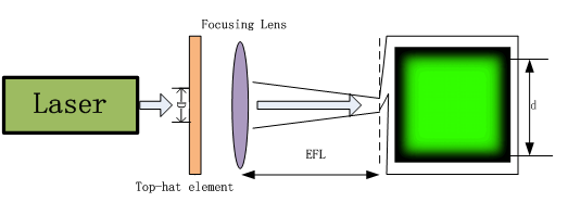
The most rudimentary set-up in a beam shaping system consists of a laser, a refractive / diffractive beam shaper element and a focusing lens. See the figure below. Top-hat elements have a high demand for laser quality. For good quality beam shaper performance, the laser output should be Single Mode (TEM00) with an M2 value under 1.3. A large M2 will degrade the uniformity and sharp edge of the top-hat spot. In this case, it may still be possible to reduce the M2 value by inserting a spatial filter in between the laser and the DOE lens component.
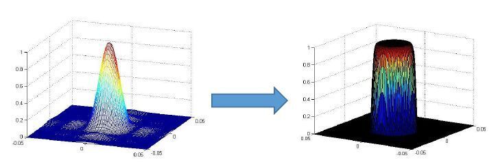
Top-hat element is a phase element that transforms the Gaussian input beam into a uniform spot with sharp edges at a specific working distance WD. Note that the Top-Hat spot is NOT at the minimum spot location (minimum waist), but near it (about a few microns from the focal plane).
Each top-hat element is designed for specific use with a unique set of optical system parameters provided by our customers:
lLaser wavelength
lInput spot size
lWorking distance
lOutput spot size
Beam shaper elements are sensitive to various parameter tolerances. Altering any one of the vales in this parameter set will degrade the performance of the Top-Hat beam shaper element, and possibly render it useless.
We highly recommend a beam expander and collimator in using top-hat element. a larger beam reduces the sensitivity of the beam shaper output to tolerances, and enable achieving a smaller output spot.
As was mentioned above, the beam shaper element requires that the input beam will be collimated.
For this reason, as well as for purposes of stability, it is recommended to work with the beam shaper element in the waist of the laser. Nonetheless, if the beam has a small divergence angle (<1º), which means, due to some constraints, the diffractive optical element (DOE) will be located at a distance from the beam waist, there should not be any noticeable effect on the Top-Hat output quality, it will though change the working distance. In short, it is more convenient to design a DOE and get the ideal performance based on an accurate high-quality wavefront
When designing the desired output Top-Hat size, it is important to be familiar with the physical limits of the minimum spot size. The formula for the diffraction-limited spot size:

Where:
L:working distance
D:input beam size(on the focusing element)
Some basic rules:
lIt is impossible to get a Top Hat size smaller than the diffraction limited spot size.
lthe minimum beam shaper spot size will be between 1.5 to 5 times the diffraction-limited spot size.
lThe best performance will be obtained for a well-positioned perfectly aligned part, located precisely in the plane of the nominal working distance.
Characteristics

Operating principle
Minimum top-hat optical element (hereinafter referred to as the element) is a product of Beijing HOMOlaser S&T CO., Ltd with a fully independent patent, which is used to focus a Gaussian beam with M2<1.5 to a well-defined size and shape with uniform intensity (flat top).The element. The element has such advantages as simple installation, high transmittance, conservation of initial optical systems.
Here is the procedures of installation and adjustment.
A.Galvanometric system
1.Conditions: a galvanometric system, a lens mount,an x-y adjuster
2.Procedures of installation and adjustment
Firstly,collimate and expand laser beam to get the required spot size by the element.
Secondly,Conventional optical adjustment makes galvanometer system achieve its conventional capabilities.
Thirdly,put the element between the beam expanding collimator and the galvanometer. Beam divergence conserves in a few meters.
Fourthly,roughly adjust the element to locate the center of it in the optical axis of the system before turning on the laser.
Fifthly,put on anti-laser goggles,turn on the laser,make the beam illuminate a piece of A4 paper,adjust the laser power until a spot is visible.
Sixthly,put the A4 paper behind the element wearing the anti-laser goggles,observe carefully to get the projection of the central pattern on the element. For example,the projection of square top-hat element is a square spot, the projection of circular top-hat element is a circular spot. Based on the location of the projection, adjust the location of the element to make sure the center of it is in the optical axis of the system. For round shape top hat element, no rotation is needed in the θ dimension, because the shape is in tune with the laser’s. While it is still necessary for other elements.
Seventhly,fix the element after all the adjustment is complete.
Eighthly,increase the laser power and make a proof. The top hat spot shows in the vicinity of field lens’ focus. It is highly recommended to prepare a Z-axis positioner to find the right position of top hat spot efficiently. Customers may adjust the positioner, make a number of proofing in a range of distance from the focus and observe them with a microscope.
B.Galvanometer-free system
1.Conditions:focusing lens,an x-y adjuster containing both the focusing lens and the element.
2.Procedures of installation and adjustment
Firstly,attach the element to the focusing lens,and then put them in the adjuster.
Secondly,put the element behind the beam expanding collimator,at the location specified by customers themselves. Beam divergence conserves in a few meters.
Thirdly,roughly adjust the element to locate the center of it in the optical axis of the system before turning on the laser.
Fourthly,put on anti-laser goggles,turn on the laser,make the beam illuminate a piece of A4 paper,adjust the laser power until a spot is visible.
Fifthly,put the A4 paper behind the element wearing the anti-laser goggles,observe carefully to get the projection of the central pattern on the element. For example,the projection of square top-hat element is a square spot, the projection of circular top-hat element is a circular spot. Based on the location of the projection, adjust the location of the element to make sure the center of it is in the optical axis of the system. For round shape top hat element, no rotation is needed in the θ dimension, because the shape is in tune with the laser’s. While it is still necessary for other elements.
Sixthly,fix the element after all the adjustment is complete.
Eighthly,increase the laser power and make a proof. The top hat spot shows in the vicinity of field lens’ focus. It is highly recommended to prepare a Z-axis positioner to find the right position of top hat spot efficiently. Customers may adjust the positioner, make a number of proofing in a range of distance from the focus and observe them with a microscope.
Notification